
Jeticopter May 5th 2024
Things have been quiet on the Jetex blog front lately and recently Roger gently nudged me and suggested an update might be in order. I will say I’ve not had that much time for model flying and development of late due to some outside interference. In fact one of my ideas for the Jeticopter somehow or other led me into making some other distinctly unJetex things. And these, while making nice presents, don’t represent progress on the Jeticopter front.

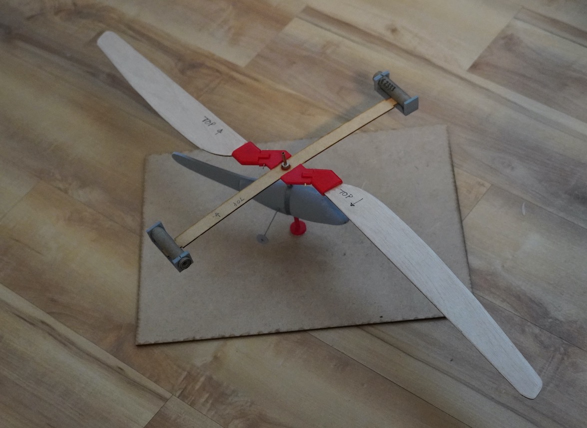
Neverthless, this is one of several earlier Jeticopter versions. It has a 3D printed fuselage from what is called lightweight PLA. The hinges, blade holders and motor holders are made from red PLA and have brass hinge pins.
One of my goals with the Jeticopter, or the Terrycopter as one of the MakerLab boys christened it, is to make as many parts as possible laser cut or 3D printed. I especially wanted to eliminate the bending of piano wire, cutting of brass tube, binding with stout thread and securing with balsa cement that looms so large in the original Jeticopter instructions. To achieve this I spotted an idea called a living hinge.
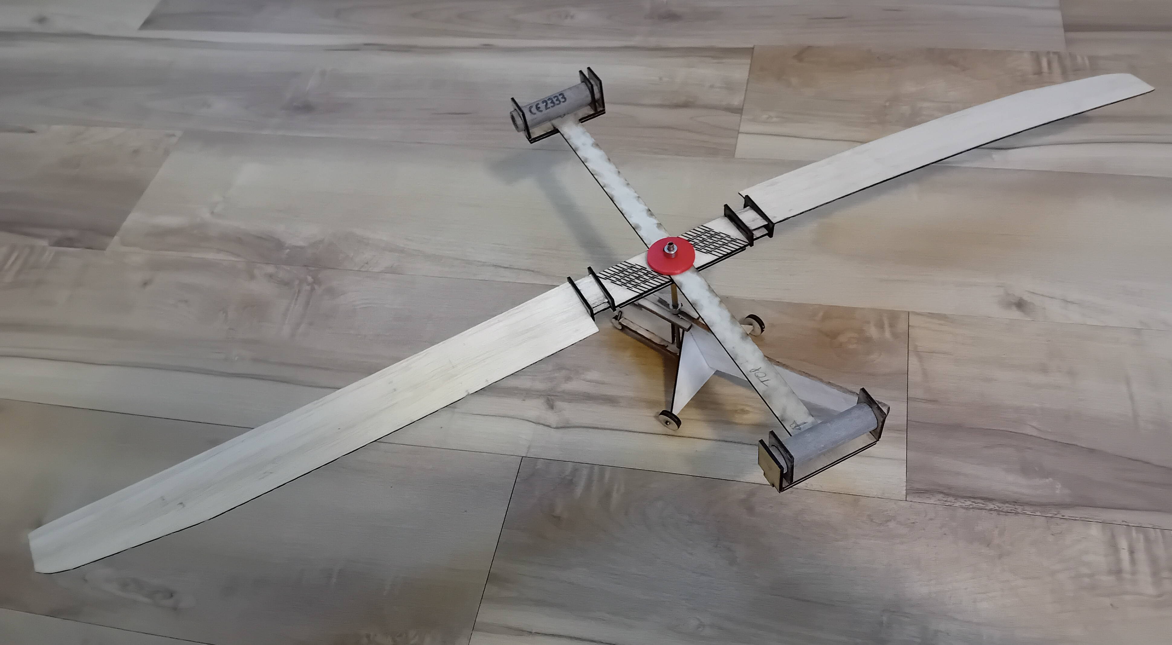
So this is a revised version which is much lighter and gets closer to the design parameters that I found in the Frank Zaic manual that I wrote about in the last blog. Here the motor holders, fuselage and the hinges are all laser cut. I’m using a combination of balsa and 1 or 2mm plywood for these parts.
Now the living hinge, which you'll see here, is a way to implement a hinge without a hinge pin. You’ve probably have encountered one of these before as they are often used in plastic boxes with integral tops. Now the idea has been extended to laser cut materials such as ply or plastic.
This entails taking a reasonably sturdy material, plywood or plastic, and cutting it in such a way that it can be bent on the desired axis. While I was playing around with the design for the Jeticopter hinge my friend Gerlinde spotted my drawings and decided that such a concept would make a nice plant holder if modified just a little.
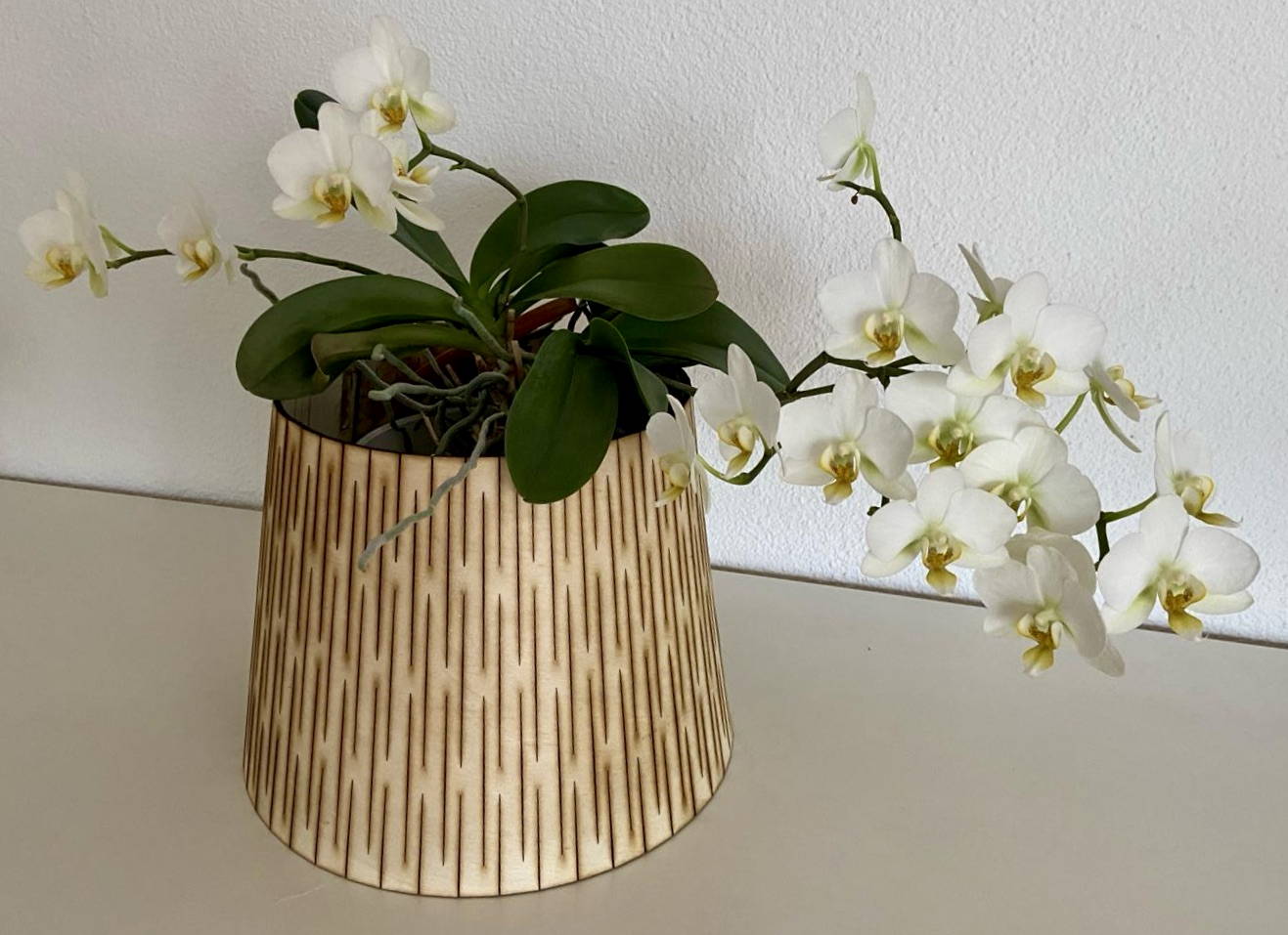
And here's one of them. These are made from 2mm thick ply.
But back to model aircraft — in the latest version most of the parts are laser cut. There’s just a couple of 3D printed plastic parts, the ones in red, a length of brass tube and 4 steel collets. The fuselage has laser cut parts from 3mm balsa or 1mm ply. The whole thing weighs in at 89gms with two unused motors. So, much closer to specifications seen in Frank Zaic’s annual.
So, all this good stuff that means there must be some snags !
Indeed so and I’m still working through these. The main issue is coming up with a cut pattern that provides sufficient ‘hinge-ability’ without compromising the shear strength of the material. As we know the whole Jeticopter concept hinges (tee hee) around the necessity for centrifugal forces to keep the rotor plane flat under power. Then, as the power phase ends the rotor disc cones up which, because of the ‘delta hinge’, gives a negative rotor angle of attack which allows an auto rotation descent. Effectively the rotor has been turned into a centrifugal governor controling the rotor blade angle of attack.
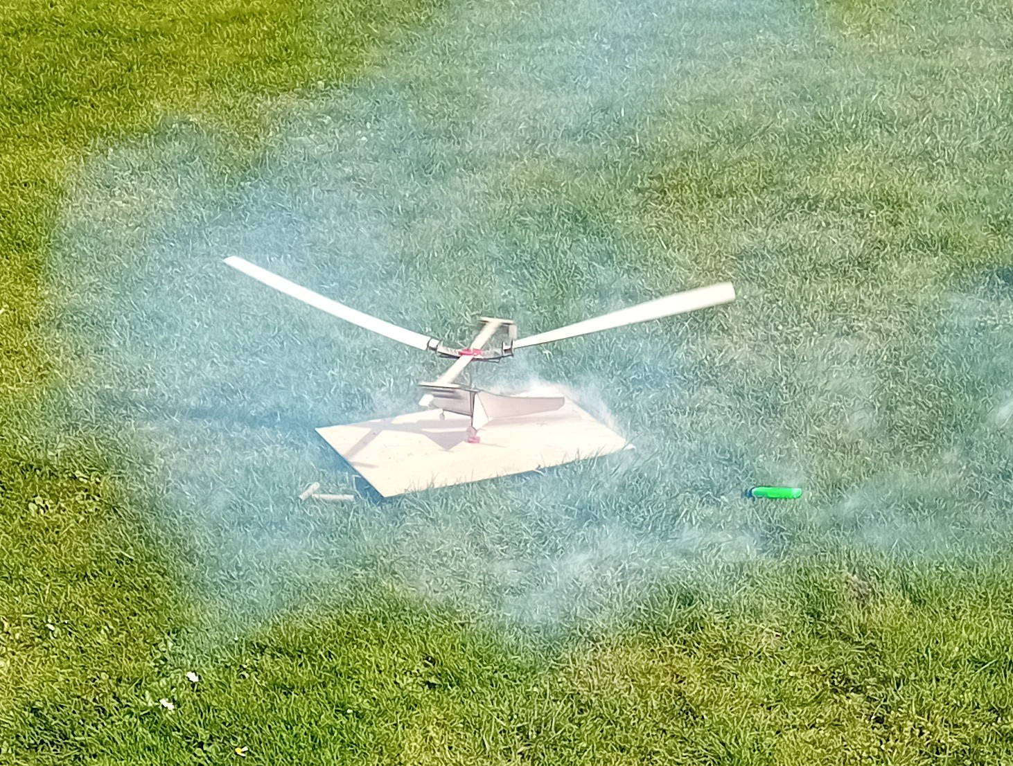
In this image we see a Tendera L2 powered attempt and as is clearly seen the rotor disc is anything but flat. The next attempts, which sadly I don’t have pictures of, followed an upgrade to L3 power. With these the rotor speed and the centrifugal force was sufficient to shear the living hinges as the rotor got up to speed! Next weeks work will include laser cutting some 4mm plastic to make a more robust hinge.
In addition I've had problems of getting both motors started simultaneously. Now, it must be said that starting Tendera motors with the green certificated fuse is way, way easier than preparing a traditional Jetex motor with gauze, spiral fuse etc. However, when one must start two motors simultaneously one starts to think, ‘perhaps there’s a better way’. I’ve been using the green fuses supplied with the Tendera certified motors and lighting first one fuse at its end and the second fuse about midway along its length - with the hope of getting a more or less simultaneous lite off of the two motors. If one has a lighter that stays lit this works fine but with cheap disposable lighters and cold days getting two lit simultaneously has not always been possible. In any event it would be nice to be able to set the model up on its launch stand, retreat to a safe distance, set the cameras rolling and flick a couple of switches to get a simultaneous double ignition every time. Ideally after a suitably stirring and dramatic, Jeff ‘Thunderbirds’ Tracey, style Five, Four, Three etc.
To this end I’ve been developing a two channel electrical ignition.
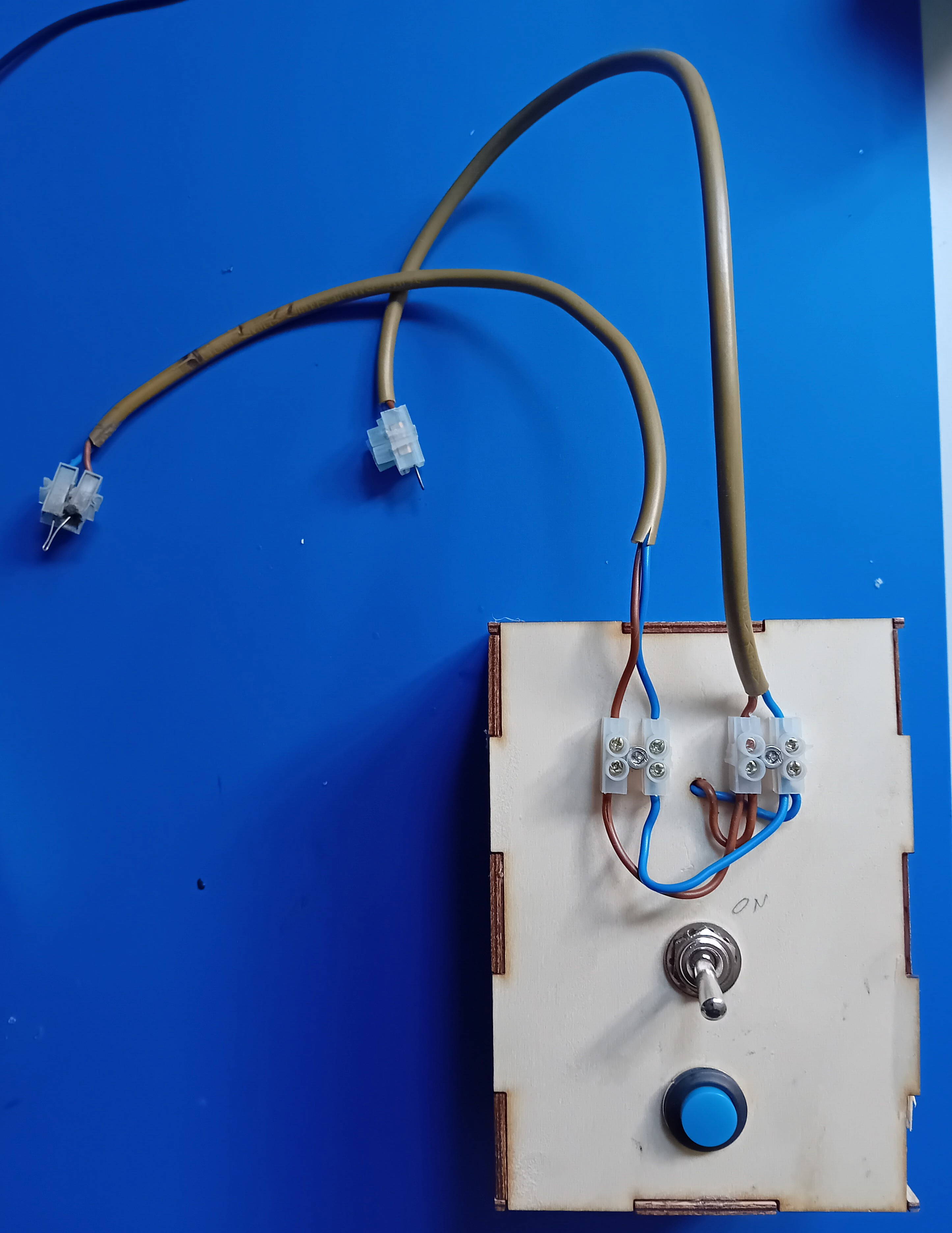
This contains two hefty NIHM cells, a circuit board so that these can be recharged from a phone charger and the switches you see here. Two loops of nicrome (resistive) wire are pushed into the nozzles and away, I hope, we go. The box is also laser cut from ply.
I’ve already concocted a simple launch stand with a vertical rod. The Jeticopter mast is abrass tube which threads over the rod. This will, I hope be rather better than hand launching with the fuselage held in the left hand while the right hand flicks frantically at the trigger of a disposable lighter trying to get the second fuse going. We'll see.
More soon...
29th January
Design Considerations
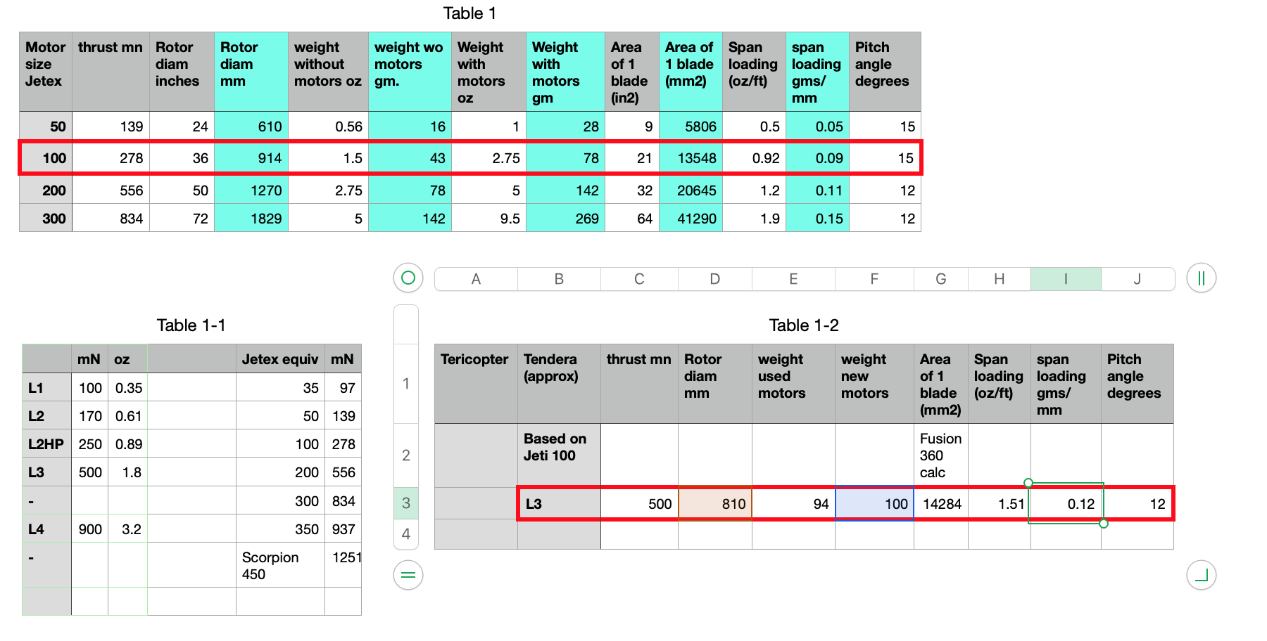
So, in my last report on Jeticopter progress I was grumbling about not having data about how much a Jeticopter should weigh. Since then I've stumbled upon, online, a very useful Frank Zaic yearbook from 1950, which as well as giving a wealth of good info of interest to the free flight fraternity, gives me some data on various Jetex powered rotary wing craft of different sizes.

Jeticopter latest. January 1st.
I've now managed several flights with the Tendera powered Jeticopter and although there's still some work to do I am making progress. Additionally, I'm finding out a few things about rotor lifted craft.
Having decided, after the earlier attempts that the model needed a considerable weight loss program, I created a new fuselage and landing gear. The new fuselage is considerably smaller and lighter than previously. Now, I haven't seen any figures for how much the various designs of Jeticopter/delta hinged rotorcraft are expected to weigh. With kit based designs, the target weight and the precise spec. of all parts is not always stated. One is expected to use the bits provided in the kit and what you get is what you get!
Anyway, with a new fuselage, 3D printed in lightweight PLA - based roughly on the Jeticopter outline and 'lofted' from the fuselage former outlines shown on the plan, I came up with a new all up weight (with used motors installed) of 102gms.
I decided to lock the rotor angle, for experimental purposes, to a positive AoA. From my earlier trials I'd thought it possible that, perhaps either the rotor was not spinning fast enough or the rotor blade mass was insufficient to ensure a positive AoA under power. - The Jeticopter hinged rotor works a little like a centrifugal governor. When spinning fast under power the rotor disc should be flat and the 'delta hinge' induces a positive AoA. At the end of the power run, as the rotor slows down, it should cone up and when it does the delta hinge induces a negative AoA. This to permit a 'autorotation' style - gentle - descent.
Anyway, with a fixed positive AoA, if the rotor was spinning fast enough and the weight low enough we should at least see an ascent ibut not a autorotation descent.
I decided to hand launch - to eliminate the possibility of the Jeticopter hanging up on the launch rod. So with two fresh L3s installed, and wearing my safety goggles, I lit the fuses (first one at the end of the fuse, second one half way down) and was pleased to see both motors striking up pretty much simultaneously.
So, holding the model by the lower part of the fuselage I raised it up and released it. There was pretty much no wind and at first the model, clearly ascending, stayed pretty much directly overhead. This made it hard to judge the height and it was only as the motor run came to an end that I was able to see that the model was maybe 50ft in the air.
Then, as the rotor slowed down the model descended until, with the rotor pretty much stopped, it flipped inverted. Now, with a negative AoA the rotor started to rotate again (!!!) and so the model reached the ground relatively slowly and was undamaged.
The interesting point here is how stable the spinning rotor is in respect to the horizon. I'd noticed earlier that regardles of launch angles and various ups and downs the rotor plane stayed horizontal. I'd put this down to a kind of pendelum stability but clearly with the inverted autorotation something else is going on. Now there isn't an abundance of technical literature on free flight helicopters (Jetex powered or otherwise) so for me the question of uncontrolled spinning rotor stability remains a mystery!
And the next test flight was equally interesting. On this one I followed the same hand launch procedure and as I was launching one of the rotor blades came adrift. Perhaps it had clipped the fuselage or my shirt sleeve. I had intended to try and photograph this attempt but at this I didn't even bother to reach for my phone.
Neverthless the model gained height and likely got almost as high as on the previous flight. This time, as the remaining single spinning roto blade slowed, there was no sign of an autorotation (inverted or otherwise) and the model simply plumeted. Much to the amusment of several bystanders „Das ist ein gutes Spielzeug.“
„So soll es nicht funktionieren!“
What can we deduce from this? Perhaps that the current rotor size is actually too great? We'd loss more weight and spin faster with smaller blades.
There's also the matter of the freely moving hinged rotors. Are we achieving a positive AoA under power? I've thought about a way of establishing this without firing off loads of motors but I haven't had chance to try this yet.
And there's still more scope in the design for weight reduction.
More on this next time.
This version weighs in at 92gms - previously 124gms.
Jeticopter December update.
Continuing with the Tendera powered jeticopter version.
Jeticopter 1st test attempt.
So, I finally got around to testing the Tendera powered Jeticopter, (or Terricopter as it has now been christened).
After finding the Jetex 50 size Jeticopter in Helsinki it brought it home to me that my ‘copter was considerably oversized for Tendera L2 size, even L2HT. However, I had provisioned for L2 and L3 sized motors so I decided to give it a go on L2 first of all.
It’s been sweltering in Munich these last weeks and I’ve been reluctant to go model flying. I’m without a car at the moment so all models and support equipment have to be hand carried to the flying area. And all the designated flying areas are well out of town. However, I told myself the very first test probably wouldn’t take long!
I’d scouted out a potential launch area within walking distance, an asphalt tennis court. Although it was surrounded by trees I guessed that getting the model stuck in a tree would be the least of my problems.
I set up in the middle of the court and was relieved to find the place was pretty much deserted. With a motor boom sized for L2 in place I threaded the model onto it’s launch rod and checked for free movement of the rotor around the brass tube.
New Jetex Plans Section!
Our new Jetex Plans section has every plan we have ever published and much more, now in one easy to use location.
Through the years, an amazing collection of plans has built up on Jetex.org. Articles were posted with various plans in them as well as pages created to link you to plans on the site based on motor size etc.
As the years went by, Jetex.orgs original site was archived but still available to allow our visitors access to the wealth of Jetex knowledge and plans that were posted. Although there, it made it a little difficult to locate that one particular plan you may have come here to find.
It was clear we needed to put all the plans together in one place, complete with a searchable index and categorised into motor size and model type. But why stop there? We searched the net and found every model we could powered by Jetex and added it to our collection!
To access, and use, this impressive collection, simply click on the Jetex Plans link in the top menu bar. Create a new account in the Jetex Plans Section here ( https://www.jetex.org/jetex_plans/register.php ) and log in to download any of the plans available. It is separate from the forum and will not work with your Jetex Forum information!
If you have a plan we haven't listed, and would like it added to our collection, simply This email address is being protected from spambots. You need JavaScript enabled to view it. it to us (as an attachment) with, if you have it, a picture of the model.
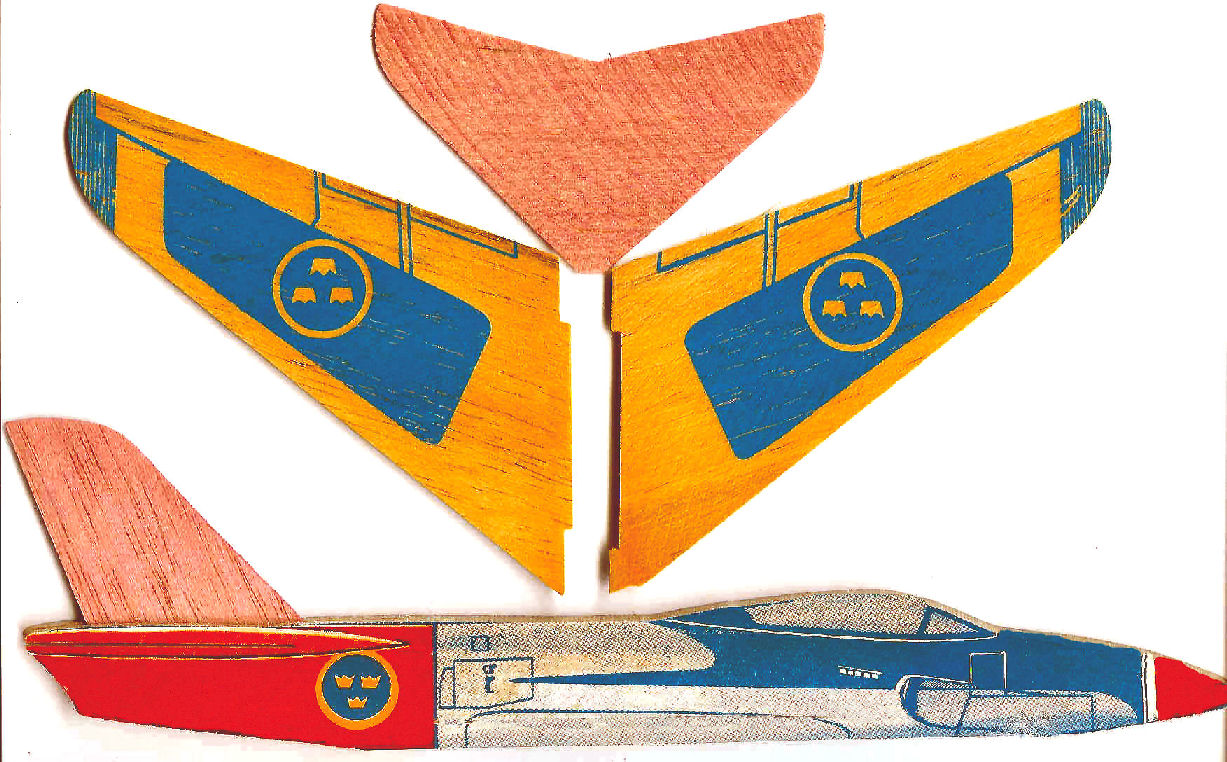
As the Jetex store is now closed, we have also decided to make templates of these kits - like the Veron 'Quickys', Keil Kraft 'Shadows' as well as the many original designs like the Draken, Mirage III and Red Arrows Hawk available as downloads so that rocketeers can make their own versions of these unique models.
Swedish Profile Jets for 2018
I am very pleased that our website has (so far) resisted all attacks and I hope the shop will soon be open for business. I'm not yet able to give the site the attention it needs - the gallery for example needs greatly expanding and I've not been as assiduous with the 'blogs' as I should be. I have also, so far, resisted all requests to go on to Facebook, Twitter, Instagram and the like!
It's not too early to be thinking about models for 2018, and, since we know what sort of motors we've got (powerful L-1's, feisty L-2X's and very nice, if low power (< 10 0mN)) L-2 LT's we can design/ size our models accordingly. As some of you will know, I have a 'thing' about the idiosyncratic Swedish jets like the Draken,and Viggen and have medelled these more than once. As to the earlier, rather more conventional Lansen, read on! Some years ago Howard Metcalfe came across a very colourful ARTF Lansen:
Page 1 of 2