
So, I finally got around to testing the Tendera powered Jeticopter, (or Terricopter as it has now been christened).
After finding the Jetex 50 size Jeticopter in Helsinki it brought it home to me that my ‘copter was considerably oversized for Tendera L2 size, even L2HT. However, I had provisioned for L2 and L3 sized motors so I decided to give it a go on L2 first of all.
It’s been sweltering in Munich these last weeks and I’ve been reluctant to go model flying. I’m without a car at the moment so all models and support equipment have to be hand carried to the flying area. And all the designated flying areas are well out of town. However, I told myself the very first test probably wouldn’t take long!
I’d scouted out a potential launch area within walking distance, an asphalt tennis court. Although it was surrounded by trees I guessed that getting the model stuck in a tree would be the least of my problems.
I set up in the middle of the court and was relieved to find the place was pretty much deserted. With a motor boom sized for L2 in place I threaded the model onto it’s launch rod and checked for free movement of the rotor around the brass tube.
A brass tube is fixed in place within the fuselage profile and it threads over a steel rod that stands up vertically from a piece of MDF which I call the launch platform. The idea being that the rotor can get up to speed first while the whole thing is stabilised by the launch rod. The model should then rise up off the rod.
I pulled out my lighter and lit, in turn, the two green fuses and swiftly retreated. Unfortunately only one fired and while the rotor started to spin it showed no sign of lifting off. But no damage was done so I could try again. (This was one of the reasons I wanted a launch rod, for the eventuality of a light up failure).
I’d left the rest of my L2s in the house but I did have another motor boom set up for L3s with me so I decided to install it and give it a go.
On this attempt both motors lit up correctly. Here I was glad of the mandated green fuse as it’s possible to light the tip of the fuse on the first motor and light the second fuse closer to its nozzle. Not too scientific but as they burn down it gives an approximation of a simultaneous light up.
The rotor spun up swiftly and the thing started to rise. However, before the it had left the top of the launch rod the whole set up toppled over and both of the, by now fast spinning blades, hit the ground and broke off.
The motor boom hit too and snapped leaving one still burning motor on the ground while the second broke free and set off to the outside of the tennis court never to be seen again.
A review of the damage revealed that the two parts that I call the blade gloves (because they hold the rotor blades) which are hinged to allow the famous Jeticopter ‘cone up’ were broken. These will need to be reprinted.
The launch rod turned out to be a mixed blessing and as I gathered my bits up I wondered about ditching it completely. But now I’ve had second thoughts.
It doesn’t need to be 400 mm long. Currently it pokes out of the top of the mast tube. So the whole thing has to lift 400 mm before its free to fly. I could make a wider base board or have a much wider launch tripod as the model rocket boys do but instead I’m going to make the next attempt with a shorter rod. Then it should serve the purpose of stabilising things while both motors get going and once it gains flying speed it can be left behind without needing to rise 400 mm.
Another thing I’ve discovered is that its very difficult to remove a spent motor from my 3D printed motor holders. I’ll need to rework these to grip the motors firmly enough but not so tightly that a spent, slightly wider motor can still be removed without breaking anything.
I’d also add that after chatting with a colleague I decided to cut some more parts for a variation where the separate motor boom is not used and the motors are mounted on the rotor tips. I haven't tried this yet but the delta hinge arrangement should still work the same way. Rotor cone flat under power and positive rotor AoA and negative after the power run is complete for an auto rotation landing.
My colleague pointed out that this is more efficient than having the rocket exhaust somewhat blocked by the following rotor blade. (Quite why the Jeticopter has boom mounted motors is something we don’t know. Perhaps I’ll find out.) And indeed this is similar to a German world war two paper exercise called the Triflugel which had a three bladed rotor with tip mounted ramjets to spin up the rotor. Roger mentioned Rob, I don’t know his last name, who had a go at a Jetex/Rapier powered version in the past.
Anyway, the first attempt went about as well as I expected and there’s a few changes to be made. It was Bram Stoker who said, “we learn from failure, not success.” Tell me about Bram!
Last week Gerlinde and I had a trip to Helsinki. Now it's not Sweden but Finland. But I hoped that the two countries had close enough ties that I would be able to find a hat such as the one worn by Sigurd Isacson in Roger's recent article. Tracking one down might have have got me back in Roger's good books and made up for all those months of delay to the rebooted Jeticopter. :)

But, despite scouring the length and breadth of the magnificent Stockman's department store I was unlucky.
I checked the markets and I went to the city library, a brand new building which is styled after a sailing ship with a roof top terrace reminiscent of a yacht's deck. In here there were robots to carry the books around and on one floor 3D printers, laser cutters, UV printers (that will print high resolution images on all manner of surfaces) and vinyl cutters which can cut the material for adding images to T-shirts. But no hat!
Eventually though I tracked down a model shop. In Helsinki the city streets are labelled in Finish, Swedish and sometimes Russian and so we picked our way through them. These are broad city streets with wheeled, autonomous robots making deliveries. And cafes with outdoor tables and heating for the comfort of the customers.
Eventually, we reached our destination and the shop was shut! I looked in the windows, and there were many plastic kits of unusual rareity. I spotted a large Heller kit of an aircraft called 'Warning Star' , a Lockheed Constallation modified for Airborne Early Warning purposes. There were several plastics of east european origin. We decided to wait and got coffee in a small cafe where 'Emerdale' was playing in english with Finnish subtitles on the TV.
On the dot of 11 o.clock the shop opened and the genial owner welcomed us inside. Then, you could have knocked me down with a feather when the first thing I saw inside was a 50 size Jeticopter!
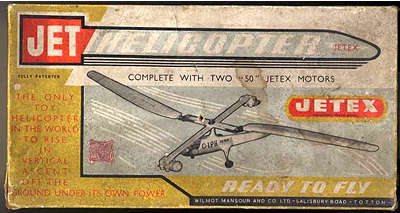
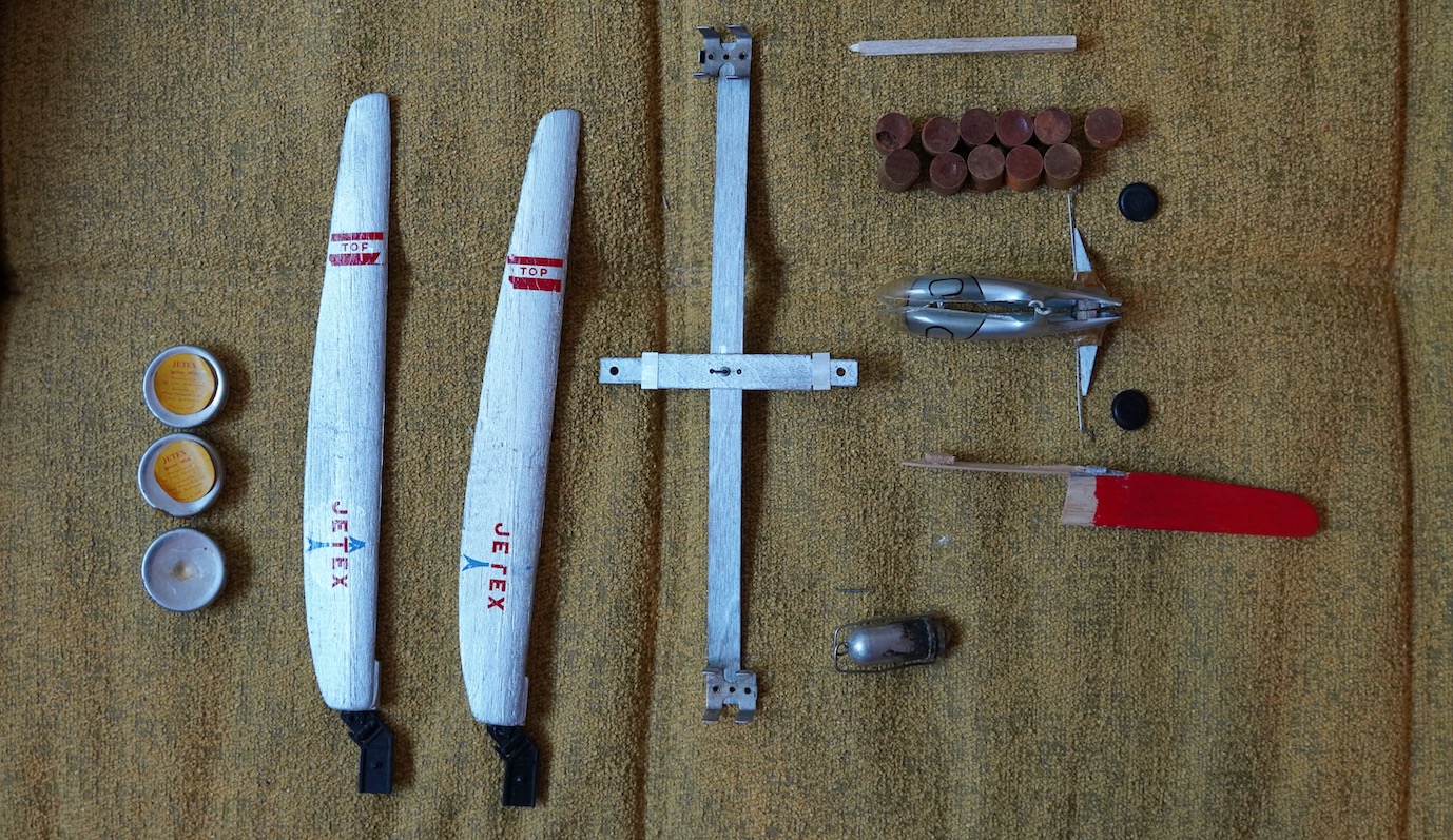
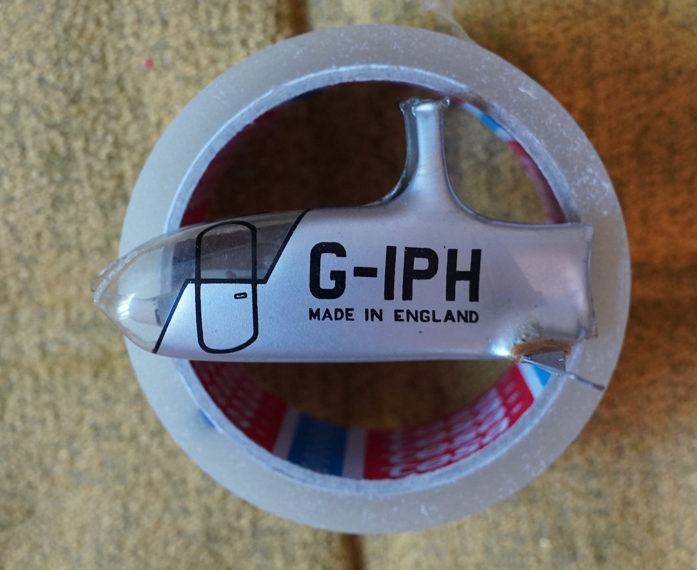
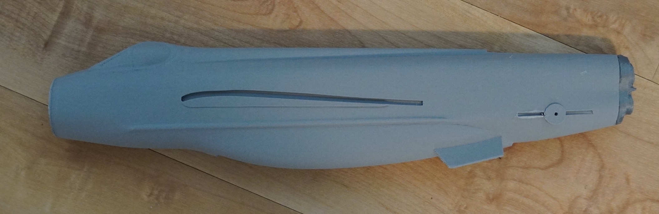
The first thing that struck me was how small it was. The individual balsa rotor blades, pre-painted and shaped were barely 230mm long. The many plastic parts, the vacuum formed acetate fuselage and the injection moulded rotor hinges were also a big surprise. (And far neater than the ones on the Terrycopter).
The box contained fuel pellets, gauzes and the various parts.
Note the very important patents on the box end.
The owner of the model shop told me he'd bought the kit in about 1960 at another Helsinki model shop, (so Sigurd Isacson influence had likely reached out) and he generously sold the Jeticopter to me at a very resonable price (after I proved my credentials by showing him Roger's recent article). But still, sadly he was unable to help with the hat. :)
Do please visit the store if you are in Helsinki. I'm not saying you'll find another Jeticopter but I'm sure you'll find some treasures.
-----------------------------------------------------------------
International shipping for Tendera motors:
Well the Tendera powered Jeticopter is slowly progressing. It's embarresing how long its taken to get to this stage and I have no excuses.
I did set myself a goal that has probably not helped - to make as many parts as possible, 3D printed or laser cut for consistency.
Additionally I tried to design the whole on screen first, then as soon as started printing and cutting out parts I thought of other, (simpler) ways to do things. So I found myself in a frequent cycle of redesign.
Classic similar designs such as the Jeticopter and the JH-3 (all available for download on your favorite website - Jetex.org) use the delta hinge arrangement which means the two main rotors have a hinge line at 45 degrees the the axis.
On the JH-3 the hinge is implimented using a combination of 0.62" music wire in 3/32 brass tube with the tube bound to the rotor root with 4 ply silk. On the Jeticopter 'strong' thread is used and much recourse, (I imagine) to smearing balsa cement over the silk/thread to hold it all together.
Up and down stops are also required to prevent the rotor 'coning up' too much on the decent. The downstops ensure that at launch the blades are just below (5 degrees) horizontal. (these are also produced using music wire).
The delta hinge idea, of course, is to ensure that under power the blades have a positive angle of attack and at the end of the power run, as the blades reduce speed, they are allowed to cone up and in doing so then present a slight negative angle to the blade's relative wind. Fullsize helicopters only adopt a negative AoA for an unpowered, emergency decent where the negative angle permits a reduce rate, autorotation descent.
Well, I'm not a big fan of bending music wire. I can never get such parts the way I like them and so I intially set out to eliminate them completly. I hoped intially to be able to 3D print a rotor hub complete with 'sockets' to contain the two blade roots. The idea was to make the part thinner print along the 45 degrees hinge line and have the compliance of the plastic eliminate the need for a mechanical hinge completly. This didn't work out as the printable PLA plastic was not sufficently compliant to allow the required angles of cone-up and down.
I eventually settled on a hinge pin implimented from a straight rod locked in place after assembly with a collet. This is the current prefered implimentation although I have also tried a piano wire implimentation with the the 3D printed hub replacing the brass tube and thread/silk arrangement. Hopefully the rod type will prove succesful as such a method should faciltate consistency.
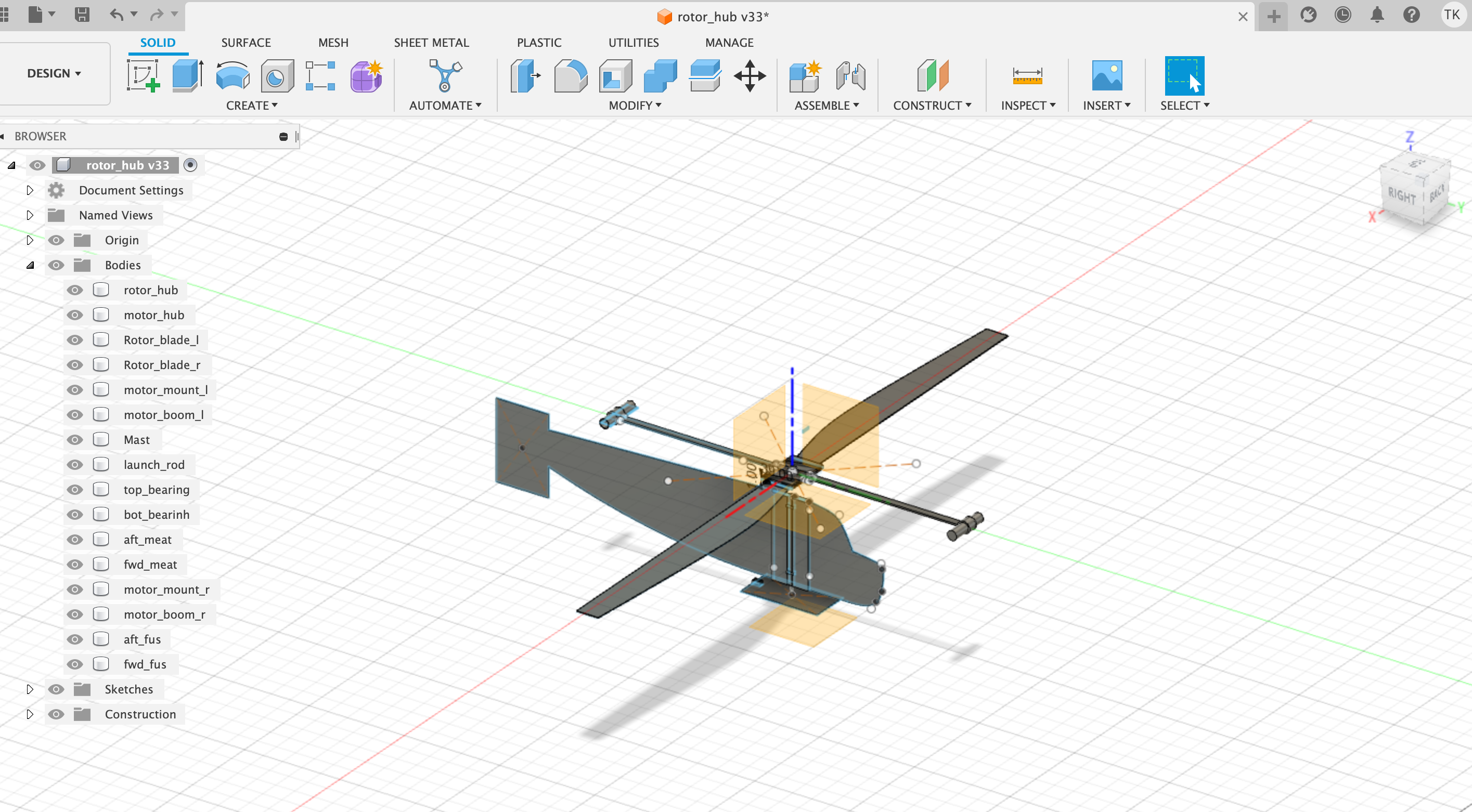
The geometry of the 'delta hinge' is such that as the hinge moves it also twists and I spent a while on Fusion 360, my CAD software, sorting out how to manipulate the parts correctly to 'model' as it were, the twisting motion.
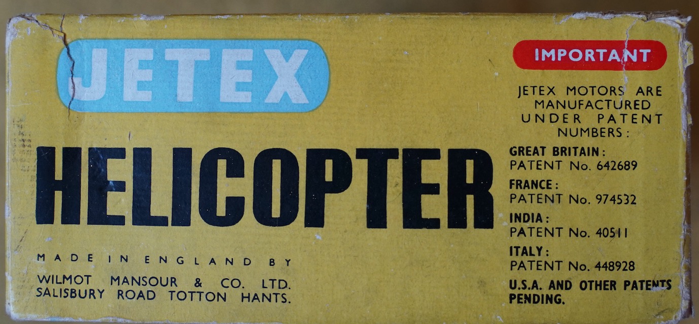
This one shows my piano wire hing version and the motor mount beam which is laser cut from 3mm MDF. (MDF is a bit of an unusual modelling material but it laser cuts nicely and is actually stronger than ply or balsa. The motor holders for Tendera L2HT or Tendera L3 are 3D printed. The fuselage will be 3mm balsa. (this is a 'profile' jeticopter.)
And of course we have a launch rod which slides into a brass tube which turns within an aluminum tube. The brass tube is pinned to the 3D printed hub with the hinged rotor blade holders hinged. The MDF motor boom will be glued to the printed hub.
The launch rod idea here is to ensure the rotor has got up to speed and 'encourage' a vertical upward trajectory, at least initially! I'll probably start off
with the standard, green Tendera fuses though I may change to an electrical system.
Still not done but we are closer now to a flight.
(I was showing a friend the classic Pathe news Jetex feature where we are told over 50 protypes were built before they had success. Yikes!!
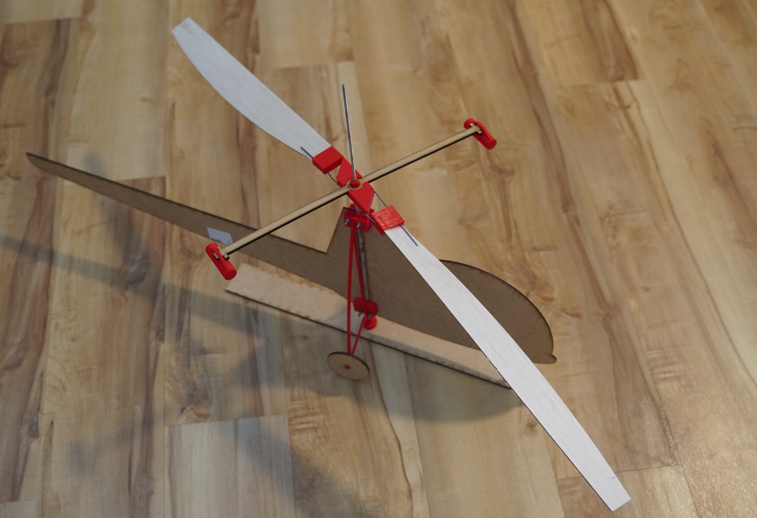
 This image is my alternate, preferred style. This uses a 2mm brass rod which is pushed into the 3D printed parts and locked in place with a steel collet. (on the other side)
My other excuse is that I distracted myself with another project - this 3D printed F6 Lightning.
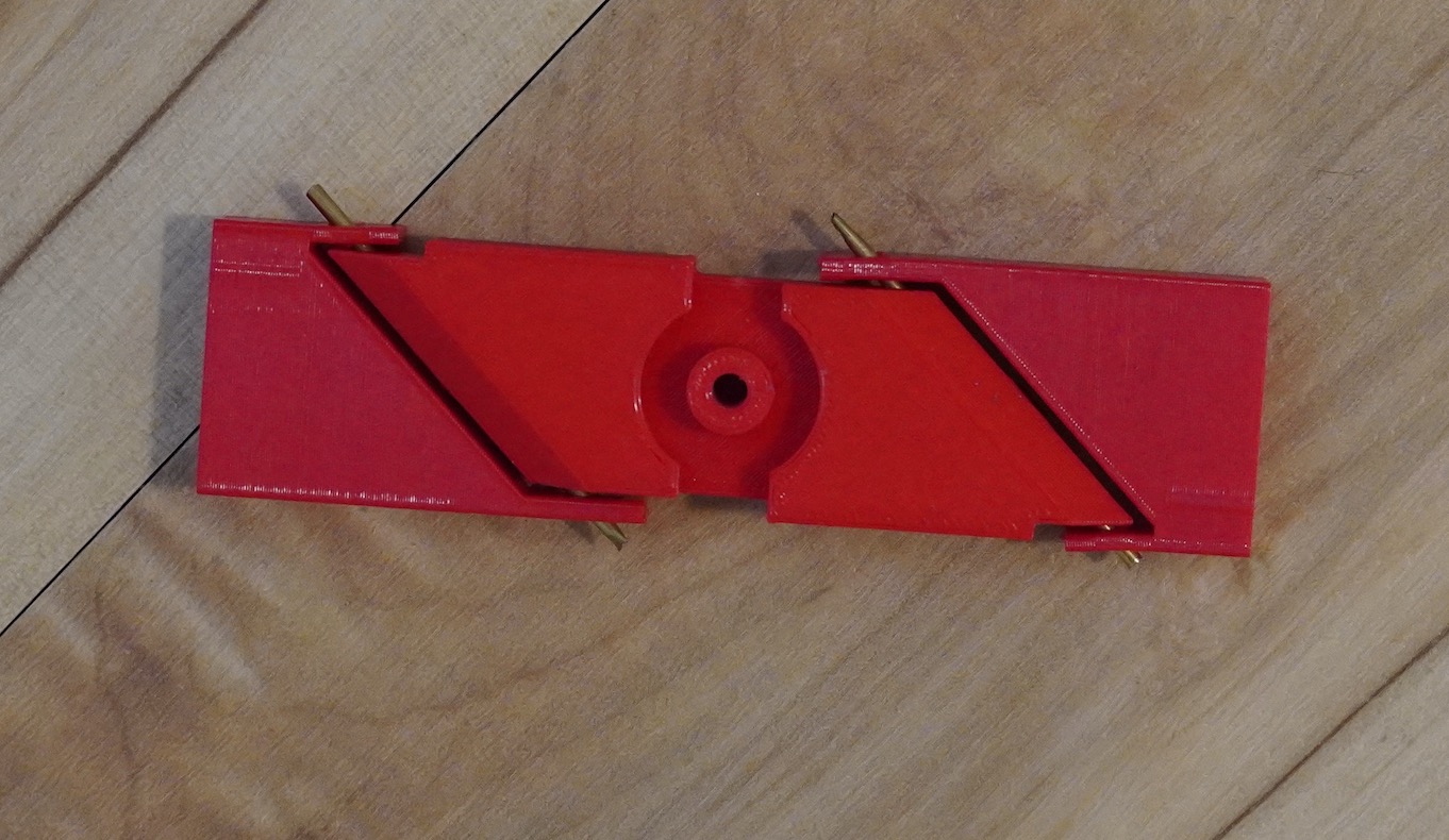
This model is derived from a Flight Simulator 3D image which I imported into my Fusion 360 CAD software and then modified for flight. In this shot you can see the slot for what will be depron sheet wings. The original Flight sim model, though pretty wasn't symetrical. When I attached the wings to the first version one was ahead of the other. I had to split the 3D model length wise in half and make a mirror image and splice the thing together again.
This revealed another problem. The original model was just too detailed. The mess image was composed of so many triangles Fusion 360 got stuck and had to be forceably restarted. F360 has a remeshing tool which can reduce the resolution but that got stuck too! In the end I had to import the original model to another tool, Meshlab and reduce the resolution using that. There's no point in having more resolution than can be noticed on the 3D printed parts and they are relatively low resolution.
The fuselage is printed using Prusa's Lightweight PLA which is lighter per unit volume than normal PLA. It simply requires a somewhat higher temperature to hit the foaming point.
In addition I'm printing using something called 'spiral vase mode.' This means the finished model fuselage is just 0.4mm thick and needs to be relatvely taller than wide. When printing the printer puts a base down first, which in this case serves has a front bulkhead. The rest of the model is hollow with an open rear. I have to seperately print the nose cone and exhausts and glue them on after the 3.25 hour print process is done.
Neverthless I'm pleased with the results.
This is my development hack. It weighs in at 48gms including a motor. It ought to be a bit lighter with the depron wings and tail feathers.
As you'll notice the extreme rear of the trough, which wasn't protected with foil has suffered. The area in close proximity to the motor where it was protected (with foil from a takeaway food container) has held up.
Jeticopter PS.
Chatting to a Spanish friend of mine who knows a bit about these rotary winged things. He suggested that it would be better to have the motors at either the rotor roots or the tips. (rather than on the beam at 90 degrees to the rotor axis.) So that the rotor is not flying directly in the exhaust. Certainly a full size heli that uses jets to directly spin the rotor (rather than through a drive shaft from a gas turbine) has the jet engines mounted outboard of the rotor tips.
https://www.youtube.com/watch?v=vMXwdGvlwDc
Such a configuration seems to offer an alternative to the delta hinge feathering arrangement. The rotors would rotate around a rotor long axis hing pin which would be at the 1/3 rd chord point of the rotor. The unused motors would be heavy enough to hold an intial positive AoA (plus a bit of exhaust up angle). At the end of the power run the rotors will/should rotate to negative AoA and provide the autorotate descent. This is a bit like those free flight hellis with a vertically mounted IC engine. These have a prop and the motor, plus fuel tank mounted on a rotor hub and turns it through torque. (F.G.Boreham had a hand in these too I think). These have blades that rotate around the rotor long axis and transition from positive AoA to negative when the engine stops. These have a weight on the blades to assist this AoA change, somehow.
Hmmm. Perhaps I ought to finish the first version before starting on this.
Well, I figured we were long overdue for a Jeticopter update. I spent much of yesterday laser cutting and 3D printing parts. Unfortunately a couple of vital components are missing from this view, namely the main rotors and the rocket motor holders.
The Jeticopter I’m copying had a couple of Jetex 100s to spin the rotor and this one, a bit bigger and heavier will use Tendera L3s which produce 500 mNs each or 1.8ozs in old money.
The Jeticopter as drawn up by messers Wilmot and Mansour has rather more recourse to bent piano wire and binding with strong thread than I’m happy with. Instead I’ve tried to use mainly 3D printed parts, some laser cut parts and such brass tube and steel rod that can be sourced in the local building supplies shop.
The so called ‘delta hinge’ which ensures the rotor blades adopt a positive angle of attack under power and feather to a negative AoA for the unpowered descent is implemented using a 3D printed hub and brass tube.
The other main difference is the launch rod. This to ensure that the thing has a little stability while the two motors are starting up.
Well, we’ll see. That’s it for now!
The TenderaCopter.
The copter will comprise some 3D printed parts, some wooden parts cut from sheet material using a Laser Cutter and some other odds and ends of tube and threaded rod which will be handworked to the required size.
I went down to MakerLab with my laptop, some balsa wood and one or two other bits and bobs. I will say I make no apologies for replicating/versioning a vintage Jetex model using CAD drawings, 3D printing and laser cutting. In their day Wilmot Mansour were innovators, with for example their ‘Tailored’ kits, I’m sure if they were around today they’d be embracing all the new technology.
The Jeticopter design features the so-called Delta hinge which allows the angle of attack of the two blades to change between power and descent. This is intended to ‘mode’ the rotor into positive angle of attack under power. Then, when the rotor reduces speed at the end of the power run, the two blades ‘cone up’ and adopt a negative angle of attack. This should permit an autorotation style descent. In the original design the hinge system is a piano wire and brass tube creation. I’m trying to use the compliance of the printed plastic to achieve the same end.
No anti-torque tail rotor is required as, unlike a conventional helicopter with a fuselage mounted motor, no torque between the fuselage and rotors exist. One or two full-size implementations have been attempted with what one might call rotor mounted thrust. The Hiller YH-32 which had rotor tip mounted ramjets. Getting the ramjets started and both simultaneously must have been quite a challenge. The Fairy Rotodyne, which used gases fed to the rotor tips from a fuselage mounted gas turbine engine is another variation.
The TenderaCopter, however, will have two Tendera long duration rocket motors at either end of a boom which is at 90 degrees to the twin blade lifting rotors. It will be launched from a small launch pad with a vertical rod rising from it. What is effectively the rotor mast is a 6mm diameter tube which, for launching, pushes down onto this rod. This tube itself turns within two ball races in the fuselage.
The rotor head incorporates a printed boss which will be drilled and pined to the mast. The two rocket motors will be on beams which plug in to another 3D printed part which interlocks with the rotor hub, to ensure that the motor boom’s motion is transferred to the rotors. This part too has a boss which pins it to the rotor mast. That is the theory, at least. As soon as the first parts were printed I started to see what I’d done wrong and started redesigning!
The first parts were to be cut with the laser cutter. So, having designed the rotor blade in Fusion 360, the design, in 2 dimensions must be exported. Fusion 360 has the ability to export a 2D .DXF file which can be used by the laser cutter.
This DXF file, effectively is a file with parameters defining the outline of the part to be cut. With the laser cutter powered up it’s possible to upload the .DXF file to the laser cutter.
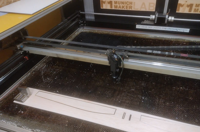
I used Microsoft Remote Desktop to connect my laptop to the PC which runs, and is an inherent part of, the laser cutter. When the laser cutter is powered up it’s PC is running an application called Lightburn which will receive the DXF file. Lightburn is also used to set the power of the laser and the speed that it traverses over the work piece. Lightburn generates a 'toolpath'. The toolpath determines the motion of the laser has it cuts the part. For my 2mm balsa the minimum settable power is used. When laser cutter has successfully imported the DXF the outline to be cut is shown on a small screen on the laser cutter’s control panel.
The material to be cut is placed in the machine and the start point, or Home position set. The material, in my case my balsa sheet which is held in place with weights which of course must be placed outside the cutting area. Then all that remains is to close the machines safety cover and press start.
Now as soon as I’d got my two blades cut out I realised I’d need thicker balsa or possibly plywood to get the required stiffness. But at least I’d got through the process.
The next job was using one of the 3D printers to produce a rotor head.
The parts to be printed need first to be exported from Fusion 360 to another utility for ‘slicing’. 3D printing is a bit like bricklaying - one must proceed a row at a time. In order to do this a file in STL format, this time representing the 3D shape of the part, must be ‘sliced’ into a series of horizontal layers.
These layers become a series of ‘tool paths’, this time for the plastic extrusion nozzle. (BTW, 3D printing is sometimes referred to as ‘additive manufacturing’ while laser cutting can be considered ‘subtractive manufacturing.’ )
So, when 3D printing is taking place the extrusion head is moved across a build surface and the desired part is built up, layer by layer. Here we encounter one of filament 3D printing’s inherent problems. - Everything is fine if we are printing a shape which rises straight from a base but any gaps, like a doorway on window in our bricklaying analogy, create a problem. The molten plastic extrudes continuously and we cannot introduce something equivalent to the lintel you’d have over a door or window gap.
It is possible to print ‘support material’ for ‘overhangs’. This prevents molten plastic being extruded into thin-air when such a gap is encountered. Without support material the extruded plastic tends to droop. And the support material can be cut-off and thrown away when the printing is complete.
For myself I tend to do what I can to orientate and design the part so that overhangs are largely eliminated. With the Buccaneer parts that I gave to Roger I introduced some additional surfaces that allowed me to print the model without overhangs. These became fuselage ‘bulkheads’ when the complete model was stuck back together.
So that in general is the process. Then, redesign and reprint or cut until a satisfactory set of parts is complete. Then assembly, test flying and doubtless redesign.
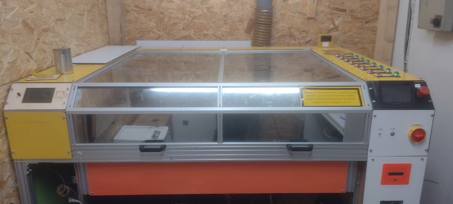
The laser cuter.
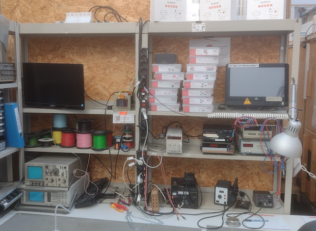
The electronics development corner.
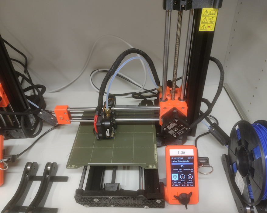
LUSA the 3D printer.
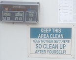
Helpful advice in any workshop.
Laser cut blades!
Jeticopter Part 1
I’ve decided to (try) and make a Tendera powered Jeticopter - or similar.
The idea is to have two motors on a beam at 90 degrees to two the lifting rotors. The lifting rotors will feature the delta hinge which provides a positive angle of attack to the rotors under power and a negative AoA for a slower decent. Additionally, as I’ve seen some problems with original Jeticopters on take off, I’m going to give the thing s hollow rotor shaft and there will be a launch pad with a vertical rod to hopefully allow the rotor to get up to speed and then guide it, initially on a vertical path.
My plan is to make some of the parts on the 3D printer and use a laser cutter to cut such parts as the rotor blades and the motor boom.
Since I recently retired and moved to Munich I no-longer have my old workshop space but I discovered and signed up with something called Maker-Lab. This is a small cooperative community run workshop which I can access for 40 euros a week. This is one of several that I’ve seen in Germany.
As MakerLab is a non-profit organisation there is a management committee , bylaws and regular meetings. One of my first visits was on the occasion of a Plenum where various issues were aired, discussed and of course minuted.
Fortunately, because most of the ‘Maker’ community in Munich consist of young people either still studying or working in various engineering undertakings and they are drawn from many nations across Europe the official language for business in the MakerLab is English. Which is fortunate for me as the only 72 year old native English speaker in the group!
Anyways, I’ve now gone through the arrival procedure, the mandatory training for 3D printing and the Laser cutter and I have my access key, (a kind of electronic tag) enabled to give me access to the MakeLab and to use the Laser cutter.
I’ve been developing the design using a Computer Aided Design drawing system called Fusion 360. (Having tried previously with the package mentioned in the 3D printed model thread, ‘Blender’. I just was not able to get on with it.) F360 allows me to create parts for 3D printing and laser cutting. As I hope eventually to make the Tendera Jeticopter, can anyone think of a better name, available as a kit it makes sense to have something of a design and manufacturing process.
|
So a bit of very welcome news to start 2023 is the news that there is a new supplier covering North America, Hummingbird Model Products. 4021 Vance Place Northwest,. Calgary, AB, T3A 0M7, run by Bernard Guest. https://hummingbirdmodelproducts.com/tsp-rocket-motors The Tendera motors will be a great addition to Bernard's range which already covers these very nice Jet catapult kits. |