 Random image Random image |
 |

FLYING WING
nitrocharged
|
 |
|
 |
 |
CREEP
| CREEP |
| Description: |
Reprinted from Model Aircraft, April 1954, p. 138
INTEREST in R.T.P. speed flying, especially with Jetex units, is spreading fairly rapidly, judging by club reports, and now with the possibility of prizes for the best speed each day at the 1954 "Model Engineer" Exhibition, interest may become even more keen.
Because it is probably the most important aspect, let us first explore the aerodynamic side of designing a Jetex speed model, and to make reference easy, each component of the aircraft will be dealt with in turn.
Wings
The mainplanes are usually very thin, having a chord/thickness ratio in the order of 5 per cent.- 6 per cent., the actual thickness being between 3/32 in, and 1/16 in. Chords are about 4 in, and below, and any advantages of using an aerofoil section are negligible. Sand wings to a symmetrical form by all means, but the precise shape appears to be of no importance.
In plan form, a tapered, swept wing looks fast, but seems to have no appreciable advantage in speed over a normal parallel chord type. However a swept wing does improve longitudinal stability and also makes line positioning a little less critical.
The mainplanes should be mounted on, or anywhere above, the thrust-line. Low wing models suffer from longitudinal instability, unless fuselage line attachment points are used. The angle of attack should be between zero and plus one degree in relation to the thrust-line. Negative angles should be avoided, of course.
Fuselage

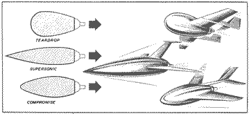
The fuselage is one of the largest drag producers on the model and in the Epsom club a great deal of controversy has arisen over fuselage design. There are two schools-the Teardrops and the Supersonics.
The Teardrops maintain that it has been proved that the best aerodynamic form for a cross section of a given area is a teardrop shape with a length/ diameter ratio of 4 : 1. Therefore, the nearer the designer can make the fuselage resemble this form the better the fuselage design.
The Supersonics favour a more carrot-shaped fuselage that tapers to a sharp point at the front. Aerodynamic arguments are vague but the bows of a ship and the Americans' X3 are quoted freely.
Well, Teardrop or Supersonic, try to cut down the cross-sectional area and bear in mind that skin friction accounts for a large percentage of the total drag. In closing this discussion on fuselage shapes, the writer has a definite preference for smooth curves … shall we continue?
Tail Unit
The tail unit is attached to the boom(s) which is rigidly fixed to the fuselage. Tailplane area is dependent on the moment arm and latest models follow the current trend of small tailplanes and long booms. It is safer to be generous with tail areas.
Fins may be omitted, but if the model flies with its nose pointing out of the flight circle, a fin will sometimes correct this, with a consequent increase in speed.
General
Finish is important on any speed model, so naturally an effort should be made to get the best finish possible. Here, the fuselage again causes problems. The walls are usually fairly thin and the heat from the unit often blisters the paintwork. A high gloss finish is useless if it is covered with blisters anything up to half-an-inch in diameter. For a long term policy it might be beneficial to leave the fuselage in a natural sanded finish, or at least dope only those portions not affected by the heat.
Reducing the wing area may add a few miles an hour extra, but it can quite easily be overdone, and the maximum speed will drop. This is caused by the wing increasing its angle of attack in order to maintain lift, and thereby increasing its drag.
Tailless models and delta planforms have proved to be very fast, but they are much more tricky to trim. Elevons are useful, but not always essential.
Lastly, arrange the design so that the unit has the maximum amount of air around the orifice, or it will never be certain that the motor is developing its best thrust.
The "Jetmaster" and the "50" unit appear to be best for this work; the larger motors do not produce anything like the same speeds, therefore, the following construction details will only apply to these two units. In general, a mixed balsa and hardwood construction gives the best results, but models have appeared with metal, plastic, and even papier-mâché components. One enterprising Epsom member once appeared with a flying saucer built from the lid of a shoe-polish tin!
Wings
Wings are best made from 3/32 in. or 1/16 in. hard balsa or 1/16 in. ply or plastic. Be liberal with the cement around the fuselage junction, but watch the plastics for warping due to chemical action.
Balsa wings should only be used on the smaller models and the line attachment point strengthened with celluloid, inset. If the line can be attached in some way to the unit itself this would be better. Holes may be drilled straight through in ply wings.
Fuselage
Balsa fuselages are quite adequate, but turned hardwood fuselages have proved very successful and- have shown a better resistance to heat, so protecting the finish. Beware of any wood that contains resin, it makes an unholy mess of the unit, if you ever get it out!
The fuselage is also the unit mount, so hollow out only sufficient to clear the body of the motor. Groove the sides to take the spring clip, making sure that the motor is not a sloppy fit. A loose unit will be ejected in the sudden acceleration of a hand launch, and a runaway motor in a small room can cause a certain amount of chaos.
Once the motor is fitted satisfactorily. the fuselage walls may be reduced to a minimum of 1/16 in, thickness.
Tail Unit
Celluloid or 1 mm. ply is suitable for the tailplane, thin celluloid being sufficient for the fin.
The tail-boom has to be light but rigid; 1/16-in. dowel or bamboo can be recommended, but keep match flames clear of bamboo, or it will soften and droop. An excessively long fuse, when ignited, can also cause the same trouble.
Trimming and Flying

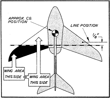
The model must be trimmed nose-heavy, and this should be borne in mind during the design stage. The method the writer uses for finding the approximate line position is this. On the plan view of the model draw a line so that there is as much wing area in front of this line as behind. The R.T.P. line should then be fixed somewhere on the aircraft about 1/8 in, in front of this line. The c.g. is then arranged forward of the line position; the exact distance is largely dependent on the design, tailless types generally having the c.g. well forward.
If the designer is ambidextrous then the direction of flight will not matter, but right-handers fly clock- wise and left-handers, anti-clockwise. Make sure the line position is on the correct wing.
Stalling, looping or an exaggerated nose-up attitude may be caused through insufficient tail area or a c.g. position near, or to the rear of, the line. Extra incidence on wing or tailplane will have the same effect. Check this and tail area, add ballast to the nose if necessary.
Diving is usually incidence trouble, try bending the boom a little or shifting the c.g. slightly rear- wards.
"Bouncing" is a mild form of dive and usually occurs at high speeds when the incidence of the tailplane probably changes a little. It can also be caused by a bad launch, so fly it again on a half charge to check this. Watch a "bouncing" aircraft carefully because the added stresses may build up sufficiently to disintegrate the model. Go over the model carefully for signs. of strained joints, inspect the line fixing particularly.
At these high speeds (75-100 m.p.h.) safety becomes of the utmost importance. If one of these models hits at 100 m.p.h. it can hurt, and the designer must do all he can to ensure that the chances of his model breaking loose are reduced as much as possible. The strain. on the model is considerable, for example a one ounce model flying at 100 m.p.h. on a 6 ft. radius line sets up a strain of six pounds in the line!

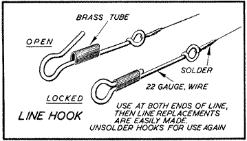
Line clips Thirty-three gauge piano wire is ideal for use as a line. See that all joints are soldered and that the hook can be locked to prevent it opening out under strain. A steel line that gets a kink must be scrapped immediately, for a kink can break easily and without warning. Reduce friction in the pole head as much as possible and hold the pole itself firmly to the floor with screws or heavy weights. The distance from the line to the floor is 18 in.
Four to five square inches wing area is sufficient for "Jetmaster" models and between three and four square inches for the "50" units. Tailless models are generally large in span, but not in area. Delta aircraft have usually a greater area. The overall length can be from one to two times the span.
You are now in possession of all the data accumulated in three years of practical development of miniature jet speed models. Don't hope to break the 100 m.p.h. limit at the first try, but the second model should be nearer to it. Experience is the best teacher. |
| Keywords: |
creep jetex 150 tinker |
| Date: |
04.01.2021 11:47 |
| Hits: |
4943 |
| Downloads: |
4 |
| Rating: |
0.00 (0 Vote(s)) |
| File size: |
49.9 KB |
| Added by: |
nitrocharged |
|
|
 |
