Here are some thoughts on why the motors are positioned as they are on Rapier and TSP powered models.
In truth this is a bit of a balancing act and the experience that has been gained by trial and error (in some cases going back over 60 years) has played a large part in determining where we put these exciting motors for our models.
For instance; on my high wing Rapier or TSP models the motor is mostly centred on or just in front of the CG so that the reducing weight of the propellant throughout the motor run does not have too great an effect on the flight path of the model.
However, on my low wing Rapier models the under slung motor is mounted forward of the CG for two reasons:
1 The vertical distance between the thrust line and the centre of drag of the model causes less looping effect than if it was a high wing model i.e. the ‘mechanical couple’ has been reduced. On a high wing model with a low mounted motor, that same distance is much greater so the ‘couple’ and tendency to loop is greater.
2 Because of 1 above, the model can be lighter as the Rapier can be moved further forward and can contribute to part of the nose weight without the model going too loopy!
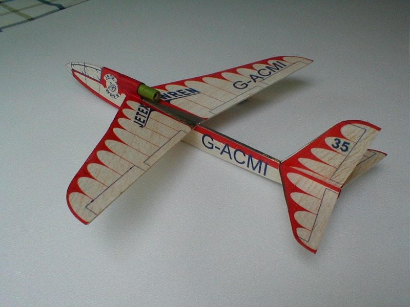
Whenever the motor hangs under the model, there is still a lesser or greater tendency to loop – which is why you will see a ‘down thrust tab at the rear underside of many models. It also explains why the Jetex Wren with a shoulder wing and high mounted motor is such a superb flying model as the ‘couple’ mentioned above works in the opposite manner against any looping effect. Note too that the motor is placed well forward of the CG which has a contribution to the nose weight of the model and in the process lowering the AUW.
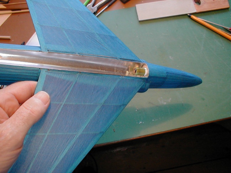
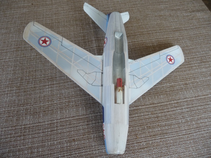
Low wing Easy Built / Aristo Craft Swift with forward placed motor
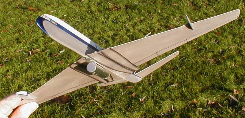
Low wing profile DH Comet, again with motor placed well forward of the CG but not too far to keep it hidden as much as possible
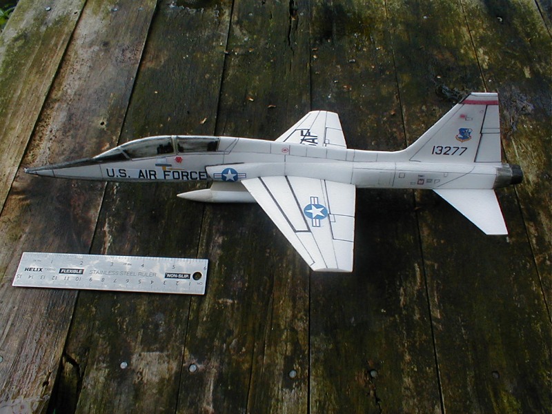
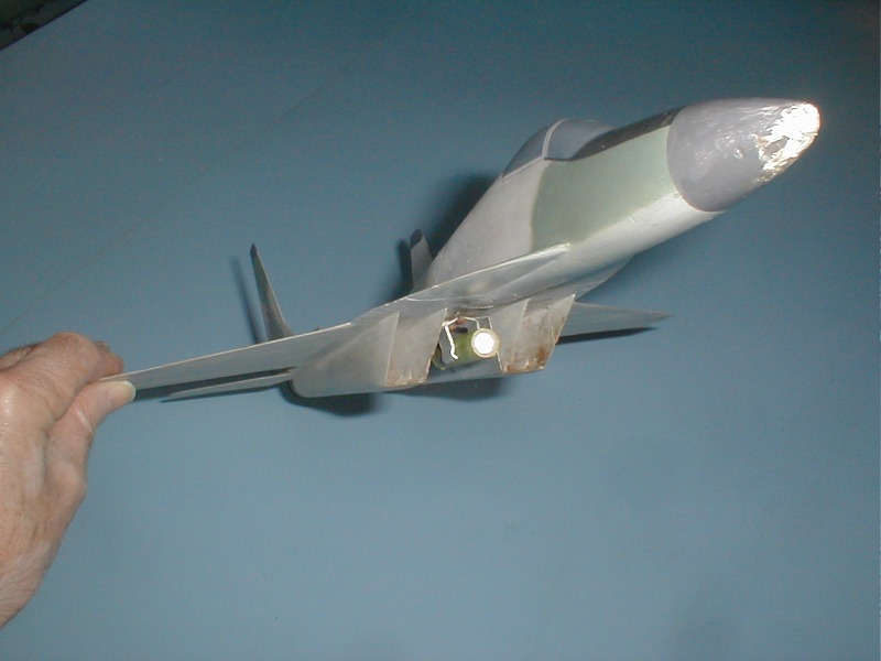
All foam low wing Talon T38 with the motor well forward
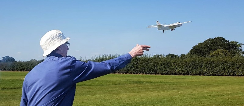
High wing foam and balsa profile Vickers Valiant with motor placed under the CG, here being launched at Old Warden. The motor was originally mounted on the side of the fuselage but this proved not to be a good idea with the varying thrust of individual motors necessitating continual re-trimming
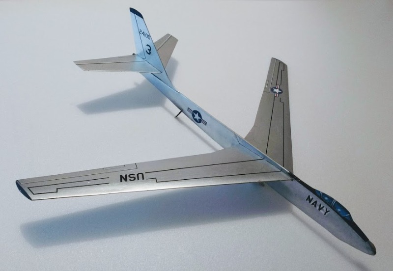
High wing balsa profile Boeing Stratojet with the motor straddling the CG. The model has knock off jet engine pods but as they are easily lost in the grass I leave them off for flying.
The superb Jetex Wren with the motor forward of the CG and above the wing